Don’t try to (needlessly) upsell me.

Writers, Print Vehicle Service Histories for Every Vehicle
read more
Don’t try to (needlessly) upsell me.
As the weather warms, more and more of your customers will be switching over their HVAC control settings to “max A/C”. If the system doesn’t respond by blowing that refreshing cool air into their faces, they will show up at your door to find out why.
When faced with an air conditioning performance complaint, the first thing I do is verify the complaint. Before I bring the car around to my service bay, I set the controls for maximum cooling: blower on high, temperature setting to full cold, recirculation mode on. I listen carefully to the sound of the blowing air as I operate the recirculation door to make sure it’s working, and then I switch airflow through all ranges to make sure the interior modes are fully functional. I place a hand over the center ducts to gauge not only the air’s temperature but also its velocity. With so many cars making use of cabin air filters, and so few of them being changed when they should be, I have solved more than one complaint by simply swapping out a clogged filter with a new one.
If the interior checks pass, but the air exiting the ducts is too warm, the next step is to pop the hood and see if the compressor is engaged. If you see that it’s not, follow some of these tips to quickly find out why.
A conventional belt-driven compressor uses a magnetic clutch to link the belt pulley to the compressor shaft. It is made up of three parts: the clutch coil, the belt pulley, and the pressure plate. The clutch coil provides the magnetism needed to draw the pressure plate inward and to keep it solidly in contact with the face of the belt pulley. Typically, the coil has a constant 12-volt power feed coming in and is operated by completing the ground side of the circuit.
The ground control on OBD-II cars rests on the shoulders of the Engine Control Module (ECM). Why? Air conditioning uses power that could be directed to the drive wheels, impacting fuel economy and emissions. Under OBD-II guidelines, that puts the ECM in charge.
However, the driver’s request for cold air may make its way through other modules before it gets to the ECM. It’s not unusual for the A/C request to originate in the HVAC control module on the dash (if equipped), only to be forwarded to a Body Control Module (BCM). Here, there will be specific criteria that need to be met before the BCM will approve the request and send it down the line to the ECM. Once the request reaches the ECM, it will have its own rules that must be met before the compressor can turn on. So, even if everything is working correctly up to this point, if the ECM doesn’t like what it sees, it will deny the driver the cold air he desired.
If the ECM approves of what it sees, it will close an internal switch (or driver) to complete the ground path for the compressor clutch relay. A relay is used in many computer-controlled circuits to protect the module from excessive current loads. The relay then acts as the control device in the clutch coil circuit, closing the path to ground and energizing the coil.

Measuring the air gap with a feeler gauge. Photo: Peter Meier.
However, if this gap is too big, the magnetic field may not be strong enough to engage the clutch at all. For that matter, if there is any factor that prevents the magnetic field from reaching its designed strength, the clutch will slip under load or not engage.
Now what could go wrong with that?
How do you handle this scenario? One good place to start is at the relay. The relay must be activated by the ECM before it turns on the compressor clutch coil. If I can determine which of the two is not happening, I can get a quick idea of where the problem lies. But is swapping the relay with one you have lying on your toolbox the best idea?
There are some problems with that. First, when a relay is turned off, there could be a kickback voltage generated by the collapsing magnetic field in both the relay coil and the compressor clutch coil that could find its way back to the ECM. That’s why some relays and coil circuits have a diode installed. If you swap the suspect relay with another that isn’t the same, you could be opening the door to a circuit board-damaging spike that may cause a failure of its own. And if the compressor doesn’t come on after the swap, what have you learned? You’re still unsure whether the problem lies in turning the relay on (the ECM side) or in the relay being turned on (the compressor clutch coil side).
Take a moment to look at the wiring schematic for the car you’re working on and identify the fuse(s) that power the compressor clutch coil and relay. Often, it’s a duty handled by one fuse, and that makes this technique even easier. Remove the fuse and install a fused jumper wire so you can use your low amp clamp to measure the current passing through the circuit. If you don’t have a low amp clamp, you can use the amp function of your Digital Volt Ohm Meter (DVOM) instead. Just be sure to set the amp scale to the 10 amp or higher range.
(Note: This technique can be used on any relay-controlled circuit, but before you use your DVOM, be sure that the normal circuit current does not exceed the capability of your tool.)

Once you’re ready to measure the current flow, start the car and turn the air conditioning on full blast. Now check your current reading. You’ll have one of three potential readings to work with.
Current won’t flow if the circuit path is not closed. And what could cause the relay circuit not to close?
Verify there is power at the appropriate relay terminals in the junction box. If not, look for an open power supply between the relay and the battery. Yes, I know it’s tempting to jump the relay terminals to see if the compressor comes on, but that will only verify what you already know. You can, however, swap the relay with another to see if the internal coil of the original relay is the cause of the open circuit. Or measure the resistance between the two coil relay terminals with your DVOM.
If the power side of the relay circuit is intact and the relay test passed, you can switch your attention to the ECM. The ECM is not completing the ground path. But before you condemn the ECM, hook up your scan tool to see if the inputs needed by the ECM to allow the compressor circuit to be completed are correct. Examples of potential problems include system pressures below specification due to refrigerant loss from a leaking component, misreporting by an input sensor (especially on vehicles with multi-zone systems), or a communication issue between the HVAC module, BCM, and/or ECM. Check if your scan tool has a bidirectional capability to command the compressor on. And don’t forget to consider the wiring between components. In many parts of the country, our little rodent buddies love to snuggle in a nice, warm engine compartment and seem to have an affinity for wiring harnesses.
What do you think this tells you? Current is flowing, so something must be turned on.
If you said the relay is, you’re correct. It takes very little to turn on a relay. That’s why it is used as a control device for so many components that are overseen by electronic control modules. A reading of approximately 0.50 amps eliminates the ECM side of the relay equation. The ECM has received the request for A/C from whatever string of modules is needed upstream, and it is satisfied that there is sufficient refrigerant in the system. All other required inputs have also gotten the “A-OK”, so there is no need to check scan data.
The problem is now limited to an open in the compressor clutch coil circuit. Now you may bypass the relay with another that is correct for the application to see if it is a failed relay. You can also use a fused jumper lead across the junction block terminals. Just be sure that the lead ends are the correct size for the application and you’ve identified the proper connections.
If you remove the fuse that powers the coil, you can then use the compressor-side relay junction block terminals and your DVOM to measure the resistance of the coil circuit. If it’s open, disconnect the harness connector at the compressor and measure the resistance of both wires individually, or install a test bulb in place of the clutch coil (using the correct terminal ends) to see if the bulb lights when the A/C is turned on. This will help narrow it down to a wiring issue or an open clutch coil winding.
If your first current measurement is reading in this range (and that number will vary), there is nothing wrong electrically with the compressor clutch coil. Current is flowing, the relay is turned on and working, and the ECM is happy. You are likely dealing with a mechanical issue in the clutch assembly. Possible causes are excessive air gap, damaged clutch faces, or a separated pulley. See all the time you would save now because you weren’t swapping relays or hooking up pressure gauges right off the bat?
This can also be used to monitor for intermittent engagement issues. If there’s a problem with the coil heating up and dropping in resistance (partial internal short), you’ll see the current rise. In turn, the magnetic field becomes weaker, potentially to the point where it is no longer strong enough to pull the pressure plate in.
To get an idea of what a normal current range should be, take the resistance specification of the coil and plug it into Ohm’s Law along with the actual measured battery voltage with the engine running. You do remember Ohm’s Law, don’t you? Voltage equals resistance (in ohms) times current (in amps). Let’s say, for example, the spec is 4 ohms for the coil’s resistance, and the running voltage measured is 14.2 volts. Using Ohm’s Law, you’ll get 14.2/4.0 = 3.55 amps as an expected measurement.
Now, don’t freak if it isn’t exactly right. What you’ll be looking for is a reading that is way off. I’ve already covered what a high reading would indicate. But what about a low reading? Low current indicates a high resistance issue according to the lessons of Ohm’s Law. Now you need to perform a voltage drop test right at the compressor (or as close to it as you can get). If the extra resistance isn’t in the circuit, it must be in the coil.
Want to learn more about testing A/C systems? Visit the Dorman Training Center and take advantage of the training resources our team of instructors has put together for you!
The articles and other content contained on this site may contain links to third party websites. By clicking them, you consent to Dorman’s Website Use Agreement.
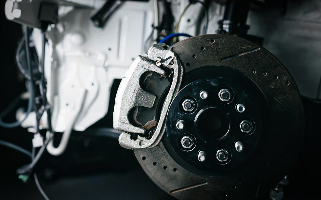
Regenerative systems slow the vehicle electrically, but the reduced use of friction brakes creates new maintenance challenges.
A/C systems are evolving with new designs and refrigerants, making accurate diagnosis and repair more important than ever.
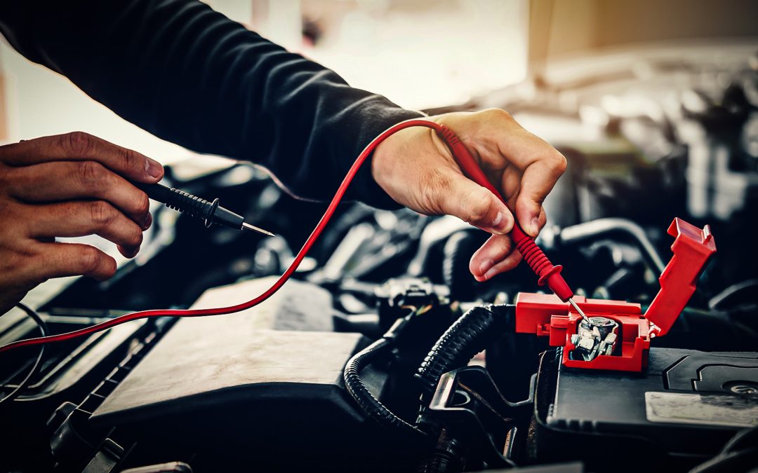
Draw a hard line when it comes to basic diagnostics.

Technician A says thrust angle must be set to zero on many ADAS-equipped vehicles during alignment. Technician B says the steering angle sensor and front wheel position must be correct before camera or radar calibration. Who is correct?
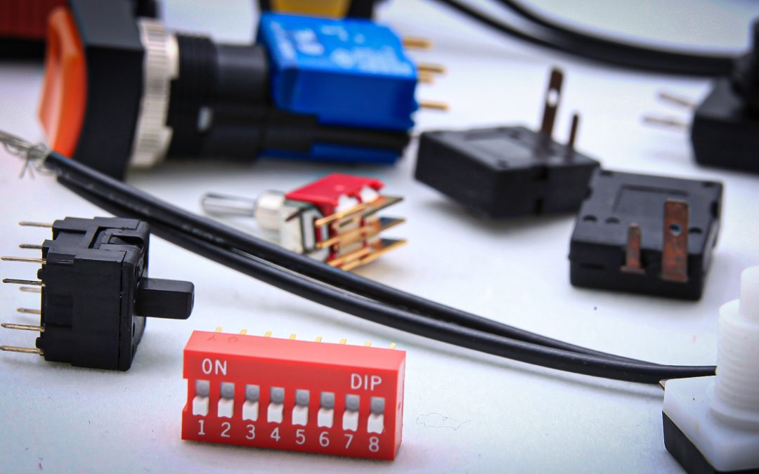
They may look simple, but these little toggles can enable powerful electronic versatility.
Loaded knuckles streamline wheel bearing and suspension repairs to help shops boost efficiency and profitability.
Participation in this forum is subject to Dorman’s Website Terms & Conditions. Please read our Comment Policy before commenting.